Read this before you start
This tool reads and, on supported packs, modifies battery BMS data. Batteries store a lot of energy — always follow the wiring guide below and work safely. Incorrect wiring or use can damage the battery or the Arduino.
Use this software at your own risk. It is provided as open source (GPL-3.0) with no warranty. It is an independent project.
What you need
A handful of parts, no soldering required for a first test.
- Chrome, Edge, Opera or Firefox on desktop Web Serial works in these browsers on desktop (Firefox 151+). Safari isn't supported.
- An Arduino Uno or ESP32-C3 with a USB cable A genuine or compatible Uno with the optiboot bootloader, or an ESP32-C3 SuperMini. The uploader flashes either automatically.
- A few jumper wires and resistors The Arduino OBI interface is just a one-wire link with two pull-up resistors — see the schematic below.
- A supported battery Currently the LXT 18 V packs (BL18xx / BL14xx) via the Arduino OBI interface.
The wiring
The Arduino OBI interface bridges your board's serial port to the battery's one-wire data line.
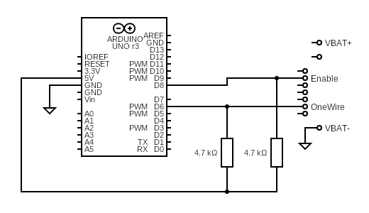
Arduino Uno
| Signal | Pin | Notes |
|---|---|---|
| Data (one-wire) | D6 | Pulled up to 5 V through the schematic's resistor. |
| Enable (EN) | D8 | Drives the battery's enable line when a command runs. |
| Power | 5 V / GND | The interface is powered from the Uno's 5 V rail. |
ESP32-C3 (SuperMini)
| Signal | Pin | Notes |
|---|---|---|
| Data (one-wire) | GPIO1 | Pulled up to 3.3 V — never 5 V. |
| Enable (EN) | GPIO0 | Drives the battery's enable line. |
| Power | 3.3 V / GND | The interface is powered from the ESP's 3.3 V rail. |
On the battery side, connect the interface's data and enable wires to the corresponding pads of your pack's communication connector (typically labelled D1 and D2) and a common GND. Exact pad positions vary between packs — check the upstream documentation for your model.
Read this before you wire anything
On an ESP32-C3 the pull-up resistors must be connected to the 3.3 V pin — connecting them to 5 V will fry the GPIOs and destroy the module.
Batteries store a lot of energy. Work with one hand in your pocket, never short the terminals, and double-check every connection before powering anything up. Incorrect wiring can damage the battery or your board.
Use this software at your own risk. It is provided as open source (GPL-3.0) with no warranty.
Next steps
Once the interface is built and wired, you're minutes away from a diagnosis.
Flash the firmware
Plug your board into USB and flash the Open Battery Information firmware straight from the browser — no Arduino IDE needed.
Connect the board
Open OBI-1, pick your board, and press Connect. It resets and identifies itself automatically.
Read the battery
Insert a battery, press Read battery, and see cell voltages, temperatures, charge cycles, and status at a glance.